When it comes to Software for CNC Plasma you can break things up into 3 distinct categories: CAD or ART, CAM, and Machine control.
CAD / ART is where you will be designing the part or artwork that you
will be cutting. This can include making a complex bracket or support
to taking an image of your favorite car and turning it into something
that you can cut. Very few programs do both CAD and ART perfect.
Most are suited to one other the other and its not uncommon to use
multiple programs in this category when doing CNC plasma cutting.
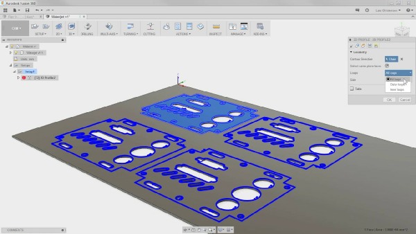
Next comes CAM, Computer Aided Manufacturing. After you have
created a part or object you want to cut you export that in a file format
that ends in .dxf. This is the most popular CAD file format for machines
to use. Once you have a .dxf file you import it into your CAM Program
this is where you will set up the tool path requirements so the machine
will know what its going to do and how to do it. To break this down in
simple terms: This is where you will tell your machine what material
your going to be cutting, how thick it is, where you want it to cut, start
and stop. All of the speeds, cut height, pierce height and plasma
cutting machine options come into play here. Your software will allow
you to build “tools” each tool can be a different material and thickness.
You can get the values for these from your plasma cutter manufacture.
I had a Hypertherm Powermax65 on my last table and my new Westcott
table has a Hypertherm Powermax85. Hypertherm is the best when it
comes to cut charts and data and they make setting up your tools and
cut information very easy. No guessing or trial and error like other
manufactures. When plasma cutting your machine will need to know
if its cutting on the inside of your lines, on your lines or outside your
lines. Simply if you have a bolt hole you want it to cut inside the line
so the hole is cut out. If your making a part you will want it to cut on
the outside of the finished part line. This is also the program that
creates your “lead ins” A lead-in is a small line that connects to the
line you want to cut. When your plasma cutter does its initial pierce
to start cutting it will make a hole which will be larger than the
subsequent cut line. This hole is not desirable to have in your finished
part so we create lean-ins so that the hole is not part of the finished
part. This will all become more clear as we move through this process.
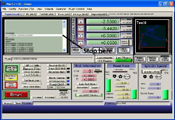
Machine Control, After your part is designed and exported as a .dxf file
you import it into the CAM program and create your tool path. Once this
is done you export this as GCODE. Gcode is the machine language that
takes all of the information you have created and turns it into
something that the machine can understand and work with. In Plasma
Cutting you will have X motion which is usually left to right, Y motion
which is usually front to back on a table and Z motion which is the height
of your torch up and down. The steppers or servos that are driving your
machine need to know where to go and when and how fast. The plasma torch also needs to know when to fire, cut, pierce, and how long to stay on and how many amps to use. There are a ton of things taking place nearly instantaneously and the Gcode is the direction to make that happen. Gcode has to be matched to your machine and equipment. You can not take gcode from someone else's machine and use it on yours unless they are exact copies.
Click on the links below to learn more about the different Software Categories and programs.
DESIGN SOFTWARE CAD / ART
CAM SOFTWARE
MACHINE CONTROL SOFTWARE
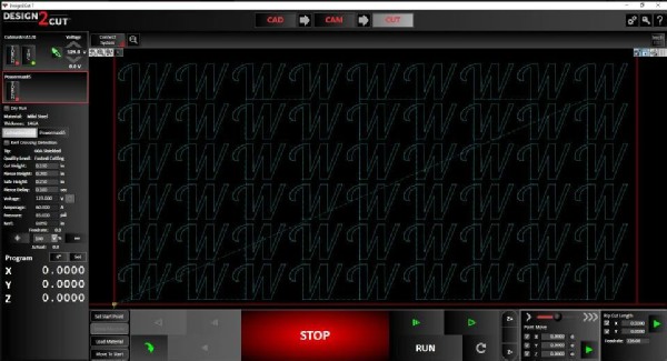
Design2Cut